• Specification
    • 1. Introduction
    • 2. Basic concepts
    • 3. Data structure description language
    • 4.1 CAN bus transport layer
    • 4.2 UDP bus transport layer
    • 4.3 MAVLink bus transport layer
    • 4.4 CANFD bus transport layer
    • 5. Application level conventions
    • 6. Application level functions
    • 7. List of standard data types
    • 8. Hardware design recommendations
    • dsdl
      • ardupilot
      • uavcan
  • Implementations
    • Libuavcan
      • Platforms
      • Tutorials
        • 1. Library build configuration
        • 2. Node initialization and startup
        • 3. Publishers and subscribers
        • 4. Services
        • 5. Timers
        • 6. Time synchronization
        • 7. Remote node reconfiguration
        • 8. Custom data types
        • 9. Node discovery
        • 10. Dynamic node ID allocation
        • 11. Firmware update
        • 12. Multithreading
        • 13. CAN acceptance filters
      • FAQ
    • Pydronecan
      • Examples
        • Automated ESC enumeration
        • Dump All Messages
        • ESC throttle control
      • Tutorials
        • 1. Setup
        • 2. Basic usage
        • 3. Advanced usage
        • 4. Parsing DSDL definitions
    • AP Periph
    • Libcanard
    • dronecan dsdlc
  • GUI Tool
    • Overview
    • Examples
    • User guide
  • Examples
    • Simple sensor node
  • Discussions
Specification /  5. Application level conventions

Application-level conventions

ID distribution

Message type ID

The valid range for message type ID is from 0 to 65535, inclusive (see CAN bus transport layer specification). The range is segmented as follows:

ID range Purpose
[0, 20000) Standard message types
[20000, 21000) Vendor-specific message types
[21000, 65536) Reserved for future use

Service type ID

The valid range for service type ID is from 0 to 255, inclusive (see CAN bus transport layer specification). The range is segmented as follows:

ID range Purpose
[0, 100) Standard service types
[100, 200) Reserved for future use
[200, 256) Vendor-specific service types

Node ID

The valid range for node ID is from 1 to 127, inclusive (see CAN bus transport layer specification).

The values 126 and 127 are reserved for debugging tools and should not be used for real nodes.

Coordinate frames and rotation representation

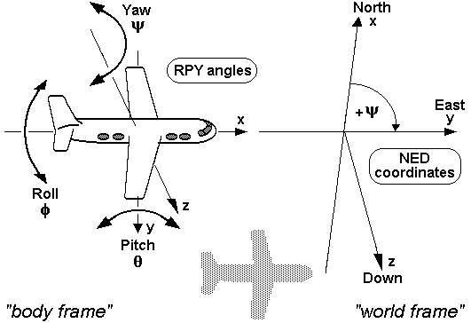
DroneCAN follows the conventions that are widely accepted in various aerospace applications.

All systems are right handed. In relation to a body, the standard is as follows:

  • X forward
  • Y right
  • Z down

In the case of cameras, the following convention should be preferred:

  • Z forward
  • X right
  • Y down

For world frames, the North-East-Down (NED) notation should be preferred.

The default rotation representation is quaternion. The coefficients are ordered as follows: X, Y, Z, W.

Angular velocities should be represented in fixed axis roll (about X), pitch (about Y), and yaw (about Z).

Matrix representation

Matrices should be represented as flat arrays in row-major order. There are some standard ways to represent an N-by-N square matrix in a one-dimensional array:

  • An empty array represents a zero matrix.
  • An array of one element represents a scalar matrix.
  • An array of N elements represents a diagonal matrix, where each array member Ai equals the matrix element Mi,i.
  • An array of ((1+N)*N)/2 elements represents a symmetric matrix, where array members represent elements of the upper-right triangle arranged in row-major order. For example, a 3-by-3 symmetric matrix can be represented as a flat array containing 6 matrix elements in the following order: [M1,1, M1,2, M1,3, M2,2, M2,3, M3,3].
  • An array of size N2 elements represents a full square matrix.

Covariance matrix

A zero covariance matrix represents an unknown covariance.

Positive infinity in variance means that the associated value is undefined. Alternatively, in some cases, the value itself can be set to NAN (not-a-number float constant) to indicate that the parameter value is not defined. Note though that it is recommended to avoid NAN and infinities whenever possible for portability reasons.

Engineering units

All units are SI units, unless explicitly noted otherwise.

The following field naming convention is used:

  • Fields that contain values not in SI units must be suffixed with the unit name, e.g., battery_capacity_wh (“wh” is for “Watt-hours” in this example).
  • Fields that contain values in SI units are not suffixed, e.g., voltage (implying that the units are Volts).

If an application designer chooses to deviate, such decision should be properly documented.


Specification

  • 1. Introduction
  • 2. Basic concepts
  • 3. Data structure description language
  • 4.1 CAN bus transport layer
  • 4.2 UDP bus transport layer
  • 4.3 MAVLink bus transport layer
  • 4.4 CANFD bus transport layer
  • 5. Application level conventions
  • 6. Application level functions
  • 7. List of standard data types
  • 8. Hardware design recommendations
  • dsdl
    • ardupilot
    • uavcan

Contents

  • Application-level conventions
    • ID distribution
      • Message type ID
      • Service type ID
      • Node ID
    • Coordinate frames and rotation representation
    • Matrix representation
      • Covariance matrix
    • Engineering units

License

This work is licensed under a Creative Commons Attribution 4.0 International License.
Much of the content of this site is based upon prior work by Pavel Kirienko and the UAVCAN Development Team.
  • https://dronecan.org/discord
  • https://github.com/DroneCAN
  • Report a problem with this website

Generated Sun, 02 Jun 2024 21:47:21 +0000 © DroneCAN development team

  • 1. Introduction
  • 2. Basic concepts
  • 3. Data structure description language
  • 4.1 CAN bus transport layer
  • 4.2 UDP bus transport layer
  • 4.3 MAVLink bus transport layer
  • 4.4 CANFD bus transport layer
  • 5. Application level conventions
  • 6. Application level functions
  • 7. List of standard data types
  • 8. Hardware design recommendations
  • dsdl
    • ardupilot
    • uavcan
  • Libuavcan
    • Platforms
    • Tutorials
      • 1. Library build configuration
      • 2. Node initialization and startup
      • 3. Publishers and subscribers
      • 4. Services
      • 5. Timers
      • 6. Time synchronization
      • 7. Remote node reconfiguration
      • 8. Custom data types
      • 9. Node discovery
      • 10. Dynamic node ID allocation
      • 11. Firmware update
      • 12. Multithreading
      • 13. CAN acceptance filters
    • FAQ
  • Pydronecan
    • Examples
      • Automated ESC enumeration
      • Dump All Messages
      • ESC throttle control
    • Tutorials
      • 1. Setup
      • 2. Basic usage
      • 3. Advanced usage
      • 4. Parsing DSDL definitions
  • AP Periph
  • Libcanard
  • dronecan dsdlc
  • Overview
  • Examples
  • User guide
  • Simple sensor node
Specification1. Introduction2. Basic concepts3. Data structure description language4.1 CAN bus transport layer4.2 UDP bus transport layer4.3 MAVLink bus transport layer4.4 CANFD bus transport layer5. Application level conventions6. Application level functions7. List of standard data types8. Hardware design recommendationsdsdlardupilotuavcanImplementationsLibuavcanPlatformsTutorials1. Library build configuration2. Node initialization and startup3. Publishers and subscribers4. Services5. Timers6. Time synchronization7. Remote node reconfiguration8. Custom data types9. Node discovery10. Dynamic node ID allocation11. Firmware update12. Multithreading13. CAN acceptance filtersFAQPydronecanExamplesAutomated ESC enumerationDump All MessagesESC throttle controlTutorials1. Setup2. Basic usage3. Advanced usage4. Parsing DSDL definitionsAP PeriphLibcanarddronecan dsdlcGUI ToolOverviewExamplesUser guideExamplesSimple sensor nodeDiscussions